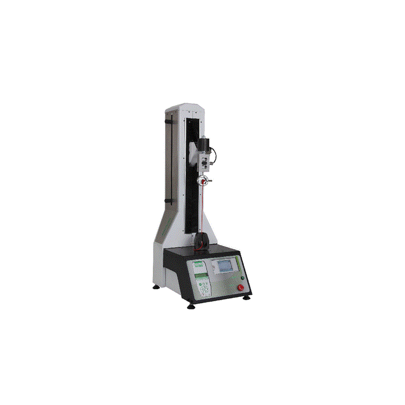
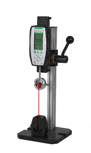
A good crimping of a terminal on a cable increases the usable life time of the connection and avoids micro cuts when using the cable in a car or an aircraft.

When do you check wire terminal crimps ?
During the manufacturing cycle and at each change of processing settings, including :
  • Checking the first batch manufactured
  • Check for each new setup of machines or crimping pliers (tool exchange)
  • Check each coil change (if terminals are supplied in a coil)
  • Interim checks (every 1000 crimps for example)
  • Check the final crimp
There are 2 types of control: visual inspection and a tensile test.

A / Visual control: This is to visually check that the terminal is properly positioned on the wire. The lug rings must be tightly wrapped around the cable, no strand shall be out of the crimping. The cable end must appear at the end of the terminal and should not be folded or bent.
Wiretest 2wiretest-2-machine-automatique-d-essai-de-sertissage.jpg
B / Tensile test: This very simple test is used to verify the correct crimp pull out force. Tensile tests are performed on a motorized test machine called a 'crimpt tester ' or' terminal pull tester' that performs this tensile test. These tests are destructive. They are performed either on pieces issued from the manufacturing process and prepared for these trials, or on samples made with wire of the same section (in the case of very long harnesses that canot been inserted on the machine.

The testing machine is equipped with a special receptacle for maintaining the terminal or utilizing a self closing grip. The cable is held by a special tool designed for not injuring the jacket. It can be a bit eccentric or self closing. Self closing grips can also be used in the case of high capacity, forces higher than 200 lbs (1000N).
The testing machine generally provides tension at a constant speed of 2 inch per min until failure of the crimp or the cable. It is also possible to use manual testers for small wires. The test sample is passed if the value found is above a reference value.


To define the reference value, there are general standards such as CEI760, or standards specific to certain industries (rail, aerospace, automotive).
The main values used are given, for guidance, in the following table :
   
Minimum pull strength
Wire size (AWG)
Wire size (mm²)
MIL-T-7928
UL 486
MIL-DTL-22520G
AWG
mm² (1 wire)
Lb
N
Lb
N
Lb
N
26 0,128 7 31     5 22
24 0,205 10 45     8 36
22 0,324 15 67 8 36 12 53
20 0,519 19 85 13 58 20 89
18 0,75 38 169 20 89    
16 1,31 50 223 30 134 50 223
14 2,08 70 312 50 223 70 312
12 3,31 110 490 70 312 110 490
10 5,26 150 668 80 356 150 668
8 8,37 225 1001 90 401 220 979
6 13,3 300 1335 100 445 300 1335
4 21,15 400 1780 140 623 400 1780
2 33,62 550 2448 180 801 550 2448
1 42,41 650 2893 200 890 650 2893
0 53,49 700 3115 250 1113 700 3115
00 67,43 750 3338 300 1335 750 3338
000 85,01 825 3671 350 1558    
00000 107,22 875 3894 450 2003 875 3894